

Click on a thumbnail for a larger image
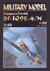
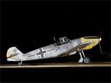
| Model: | Messerschmitt Bf-109E-4/N of JG 26, flown by Adolf Galland (Battle of Britain, 1940) |
| Kit: | Halinski Kit No. 1/99 |
| Scale: | 1:33 |
| Price: | US $6.95 Plus S&H from Paper Models International |
| Difficulty: | Difficult (4 out of 5) |
| Number of parts: | Approximately 240 |
| Time required: | About 75 hours, working slowly and deliberately, and with time allowed for reproducing and practice building some of the trickier components. |
| Instructions: | The instructions are in Polish, and they are very brief. Some of the more important points can be teased out with the aid of material on the translation page at Saul Jacob's Card/Paper Model Pages Web site. Translation assistance by Strange (a member of the CardModelers mailing list) was crucial in helping me understand the unusual wing construction for this model. (I would have gotten it completely wrong without his help.) He has generously offered to make a complete translation of the instructions available on Saul Jacob's Web site. |
| Diagrams: | Good. They occupy two 44cm x 66cm sheets. Cockpit detail is excellent. There is a need for more detailed information on fuselage, propeller, and wing construction, which is almost completely absent. |
| Fit: | Outstanding. The fit is very accurate and extremely tight, requiring careful cutting and dryfitting before assembly. If this is done, almost no adjustment or correction for poor fit or alignment should be needed. The fit is so precise, in fact, that it creates something of a problem when assembling the cockpit canopy, whose design makes no allowance for different possible thicknesses of glazing material. But from an overall engineering standpoint, this is the most impressive aircraft model I've worked with so far. |
| Coloring and Artwork: | Outstanding. The model has incredibly fine detailing, including all labels, panel replacement numbers, latches, etc. There is extensive weathering, including wear and tear on the finish, gunfire residue, oil leaks and stains, etc. The model conveys the impression of a plane that's seen a tremendous amount of action. Row after row of mission markings on the tail bear this out. The cover artwork is worth framing. Jaroslaw Wrobel must be one of the best aviation artists working today. |
| Printing: | Very good, and produced with an excellent quality of cardstock. I did notice a slight variation in color between two of the printed sheets, which creates a slight problem where parts from different sheets butt directly against one another. Color saturation also seems too low throughout, leading to a finish that seems too dull throughout. |
| Resources: | Extensive material on the Bf-109 is available on the Web, including drawings, photos, videos, animations, and detailed write-ups that cover almost every variant produced. A sampling of some of the sites I found useful, either for their content, their links, or both, include a walkaround of the Bf-109-E at Hendon's Battle of Britain museum, courtesy of the Swedish IPMS; Andreas Goldmann's extensive reference material on the BF-109; and, of course, the Virtual Aircraft Museum. Cockpit detail can be found at www.manders.fsbusiness.co.uk (which features an interactive cockpit animation), and at the Luftwaffe Resources Group's Bf-109 site (the LRG is part of the Warbirds Resources Group). Printed material on the Bf-109 is widely available through almost any library, hobby shop, or chain bookseller. I did find particularly useful Francis K. Mason's German Warplanes of World War II (Crescent Books, New York, 1983), which has an excellent drawing of an E-7 and a detailed internal construction diagram for an E-4. |
Background:
The Messerschmitt Bf-109 was born in response to a design specification issued in 1933 by the Bayerische Flugzeugwerke (hence the "Bf" in "Bf-109"). The winning Messerschmitt design first flew in 1935, powered, ironically, by a British Rolls-Royce engine. The Jumo 210A, which had been designated in the design spec, was not available in time for initial flight trials. Between the time it first took off and the end of World War II, some 35,000 Bf-109s in dozens of major and minor variants had been produced, making it one of the most extensively produced planes of the war. The Bf-109 by itself accounted for approximately two-thirds of Germany's single seat fighter production during the conflict.
The Bf-109 E series ("Emil"), upon which the Halinski kit is based, first appeared in 1938; and it became the mainstay of the Luftwaffe until the end of the Battle of Britain, when it was superseded by the much improved F series. The Emil was severely handicapped by its limited range (about 450 miles, or 660 km), and by a relative lack of manoeuverability compared to the Spitfire that it encountered over England. The Bf-109E faced a very different situation in Britain than it did against the Eastern European airforces it fought against in the opening days of the war.
Armament of the Bf-109E-4 consisted of two nose-mounted 7.9mm machine guns, two wing-mounted 20mm cannon and, optionally, a 250 kg bomb. It was powered by a DB601N engine developing 1200 hp, and had a top speed of about 350 mph (555 kph) with a ceiling of 34500 feet (10500 meters).
The Halinski kit:
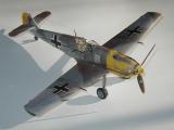
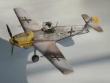
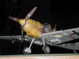
Halinski's Bf-109 is nothing less than a work of art. Andrzej Domadzierski has designed other fine models for Halinski (including a very nicely done U.S. submarine), but this one is a true masterpiece. The subject is perfect: a Battle of Britain Bf-109E flown by Adolf Galland, one of the most innovative and successful Luftwaffe officers of World War II. The fit of the components is as close to perfect as one could want, thanks to computer-aided design techniques; the sophisticated detailing outclasses anything one can find in the plastic world; and the weathering is of a quality that would be nearly impossible to reproduce in any other medium. The kit represents an amazing combination of technology and art. Of course, the builder is necessarily constrained by the designer's rendering of detail, coloring and weathering; and one's creativity will have to be expressed through the quality of construction, finishing details, and presentation. Halinski's kit gives the experienced modeler more than enough to work with in these areas.
If it is not already obvious, this is not a kit for the beginner. The part count (about 240) may seem insignificant for those whose card modeling addiction runs toward maritime subjects, where a single model may require several thousands of parts. But this number of parts is on the high side for a World War II single engine fighter, and the precise design and detailing require extreme care in cutting, shaping and fitting in order to achieve optimum results. The surface of the Bf-109 was covered with a myriad of small bumps and bulges, for example, especially on the nose and wings; and this kit reproduces them faithfully in the form of numerous small parts that need to be cut, shaped and mated to otherwise smooth surfaces. Beveling the cut edges with fine sandpaper, for example, is a good way to avoid the appearance of a "paper bump" glued to another paper surface; but it's probably not something for a beginner to start with.
In general, I would recommend this kit only to someone who has built at least two or three other aircraft models in the same scale, and who feels comfortable working with numerous small parts that build up into similarly miniature sub-assemblies. The gun sight, for example, is about 2-3mm wide, 4mm deep and perhaps 5mm tall. It is built out of five paper components (all but one of which have to be carefully folded, rounded and glued), along with a tiny piece of clear film (not included) for the half-silvered mirror! I was ready for a tweezer implant by the time I was done with it.
Construction notes:
Construction of the model can be much enhanced by using a scanner and color printer to reproduce portions of the parts sheets, if not a complete set. It is excellent insurance against loss or destruction of a part; and it also provides samples with which to practice-build some of the components that are not well covered in the diagrams and instructions. I found this essential to canopy construction, for example, as well as the exhaust ports, radiator housing and other surface features.
A number of the parts have to be backed ("doubled") with posterboard or other material before use. Three different thicknesses are required: 0.5mm, 1mm, and 2mm, marked on the parts sheets by one, two, or three asterisks respectively. Parts that need to be backed by an additional thickness of card stock (brystol) are indicated by an asterisk with a superscripted "b" (*b). I used posterboard for the 0.5mm backing, and pieces of "shirt cardboard" and thick writing tablet backing for the 1mm and 2mm sizes. Halinski sells packages of 1mm and 2mm cardboard, but I have seen nothing like that in the U.S. Scavenging seems to be a workable alternative; although I am starting to become concerned about the acid content of cheap cardboard and its possible effects on a model. I shiver at the thought of all this work turning yellow or brown in a year or two because of the cardboard backing I used.
In any event, one has to be extremely careful to adhere to the designer's requirements for backing thickness in this model. The instrument panel is built up from three pieces of 0.5mm backed stock, for example; and the slightest deviation from the proper thickness will affect how the fuselage sections mate, and how well the canopy fits. Several different thicknesses are needed for the main wheels, and their accuracy will determine how well the three-dimensional effect of a spoked wheel is rendered.
A number of small parts, especially surface fairings, wing and rudder fairings, etc., need to be formed into smoothly curved shapes. I have found that a burnishing tool, used with an old mouse pad -- the kind with a thin plastic surface and a smooth but firm foam rubber backing -- is a wonderful combination for making concave surfaces, whether fairings, cowling pieces, or other curved surfaces. Lay the part on the rubber surface and shape it by pressing with the burnishing tool. Dampening the part first with water can help in forming tighter curves.
Fuselage:
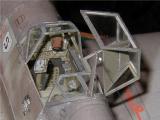
It is a good idea to begin fuselage construction by building the cockpit interior. This is a separate subassembly that will eventually be mated to a forward bulkhead and fuselage segment, and then glued inside the outer skin of the cockpit area (see photos below). The cockpit, which consists of more than 30 parts, is formed as a 5-sided box with a built-up instrument panel to the front, pilot's seat, seat adjusting lever and control column mounted on the floor, and the breaker panel, oxygen regulator, stabilizer incidence wheel, etc., mounted on the sides. It is very cramped for a space that is less than 2cm wide, and the parts have to be cut and folded to their indicated size as closely as possible if everything is going to fit comfortably inside. It helps to glue the seat assembly, adjusting lever and control column to the floor first, and then add the various components to the sides before gluing the vertical edges of the cockpit "box" together. I also added folded reinforcing strips on the outside of the rear edges to insure a true joint. To simulate the leather (or rubber) boot at the base of the control column, I used a small cone formed from tissue paper and painted a dark brown. A thin piece of piano wire inside the column served as a stiffener.
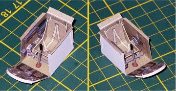 Incidentally, this is the only area where I have anything approaching a complaint with the model design. Even though meticulous care is taken to detail the instrument panel and give it the appropriate 3-dimensional shape, the area under the panel is left solid, with the rudder pedals simply printed on the vertical surface. This may have been done to insure adequate strength for the bulkhead "sandwich" to which the instrument panel is attached and which contains the root for the main spar. Nevertheless, it looks as though there would have been sufficient space and strength to allow for cutouts on either side of the central column and a floorboard to which angled pedals could be mounted.
While the gun sight (which is numbered as part of the cockpit interior) could be built at this point, it is not advisable to attach it at this early stage of construction. This is a tiny and very delicate assembly that protrudes above the cockpit when glued in place; and there is a real risk of damage if it is installed at this time. I waited until I had the windscreen portion of the canopy in place before attaching it to the control panel.
The fuselage itself is constructed using the bulkhead and connecting strip method. There are no diagrams showing construction details, but the procedure should be familiar to those who have built other models that employ the technique. The 11 fuselage segments are numbered consecutively from nose to tail; and while the usual rule of thumb is to build according to the part numbering sequence, it made more sense in this case to begin with the aft portion of the fuselage (segments 6 through 11), followed by addition of the cockpit assembly (cockpit interior mated to segment 5), and then the forward segments working in reverse numerical order toward the nose. The fit is very tight throughout, and dryfitting is critical to avoid "hourglassing," particularly in the aft segments of the fuselage.


This is probably a good time to install the various protuberances that litter the Bf-109's nose section: machine gun fairings, exhaust ports, coolant pipe fairings, supercharger intake, radiator housing, and so on. If the equipment is available, scan and print copies of the more complex parts (exhausts and radiator, in particular) and practice building them before working on the parts supplied in the kit. They mate extremely well with the fuselage, but only if the parts themselves are cut and shaped very carefully. Beveling the edges of flush-mounted parts can help. Form a small piece of fine sandpaper (I use 400 or 600 grit wet-or-dry paper) to lie flush against the fuselage, and then sand the part to be mounted against this surface (at the mounting location) until the outside edge is thin but not ragged. Touch up painting later on can eliminate any remaining white edges.
Empennage:
The rudder and tailplane can be installed at this point. The bottom of the rudder is shaped to mate smoothly with the rearmost fuselage segment. A vertical former helps to maintain the correct thickness. The tailplane spar is installed through the rudder and a vertical mounting plate that seems intended to keep all the components aligned (except that I forgot to install it). The tailplane halves are formed and mounted around the spar (see photo above). Tailplane supports are rolled hollow, and then partially flattened to obtain an oval cross-section. These are attached to small mounting flanges that should be glued in place before trying to fit the supports.
Wing:
The wings are formed around an intricate spar and rib assembly that not only shapes the airfoil, but also provides mounting and alignment for the wheel well assemblies, and an armature for the wingtips (see photo below). While the layout for the spar and rib assembly is fairly apparent from the construction diagrams and the alignment markings on the parts themselves, there are other important details that are not at all apparent from the diagrams provided.
For example, one of the illustrations shows what appears to be a large unlabeled part inside the wing -- possibly backing for one of the wing surfaces. But there is no information on material, exact shape, how it is to interact with other parts (e.g., wheel well cutouts), and so on. This is where Strange came to the rescue. He graciously offered to translate the instructions for building the wing, and his translation revealed that the mystery part was indeed a backing sheet, to be made of card stock equal in thickness to the parts sheet, glued to the bottom surface of the wing and folded at the trailing edge to mate with the top surface. Until I received his translation, I was about ready to make a simple folded mating strip to use on the trailing edge. This would have been a big mistake, since doing so would have left the bottom wing surface weakened (and badly warped) because of the wheel well cutout.
With the help of Strange's translation and a little trial and error, it is apparent that the backing should be constructed as follows: Cut each wing out first, including the wheel well cutout, but leave it unfolded. Rough out a piece of cardstock slightly larger than the wing. Put a 1/4" (7mm) fold in the trailing edge of the backing and align the result 1mm inside the trailing edge of the wing. Mark the leading edge of the backing about 2mm behind where the outer skin will be folded; this will give clearance for the cannons. Trim the outer edge 1-2mm inside the wingtip rib (otherwise, it will ruin the wingtip alignment). Cut an opening to accommodate the wheel well with about 1/16" (2mm) clearance all around. Shape the inboard side of the backing so that it will not interfere when attaching the wing to the fuselage. Once all of this is done, carefully glue the backing to the wing's undersurface, and apply pressure on the assembly until the glue has dried. (I did not do this, and some warping is apparent in the photo below. Fortunately, it disappeared when the skin was glued to the frame and mounted.)
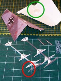
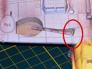
Build the wheel well assembly at this point, being sure to punch or drill holes for the retaining wire that will hold the landing gear strut in position. Glue the wheel well to the lower wing surface. Form the strut around a length of 1/32" (0.8mm) wire, formed as shown in the plans, to provide an axle for the wheel. Do the same for the tube on which the strut will pivot, being very careful not to damage the upper end of the strut. (This part rolls at right angles to the direction of the main strut.) The portion of the part that joins the two is very narrow and easily torn, so reinforcing it with cyanoacrylate (CYA) glue is recommended. Install the strut into the wheel well using the pivot wire ("D"). Use CYA glue (slow cure, if possible) to anchor the pivot wire. (Note that it will be difficult or impossible to install the strut after the wing is assembled.) A picture of the struts (before installation), and an inside view of the wheel well (green circle) are shown in the accompanying photo. The strut installed in the wheel well on a finished wing is shown in the photo below, with the pivot arrangement for the strut marked by a red oval.
Dry fit the wheel well against the cutouts in the wing ribs (red oval in the photo above), and adjust the latter if the fit is not accurate. (Some adjustment will probably be needed.) Once this is done, the lower surface of the wing can be glued to the spar and ribs, carefully fitting the strut cutout portion of the wheel well to the ribs. Tightly form the upper surface of the wing around the ribs and glue it to the folded strip on the backing sheet and the trailing edge of the lower wing surface. The far end of the wing skin (with connecting strip) should just cover the outermost rib. When this has dried, the upper and lower halves of the wing tip can be shaped and glued in place. (Note that the internal framework for the wingtip has to be beveled to achieve the proper fit and shape.
 Attach the wings to the fuselage at this point. There are cutouts in the two innermost ribs of each wing to accommodate the spar root that extends from bulkhead VI. I would suggest not applying any glue to the wing spar or the spar root, but only to the wing skin where it attaches to the fuselage. The wing assembly mates very cleanly to the spar root and fuselage (assuming that the components have been dryfitted and adjusted as needed); and the principal concern with assembly at this point should be insuring that the port and starboard wing skins mate precisely along the fuselage centerline. This will insure near perfect dihedral, and will avoid the problem of having glue set up on the spar before the wing surface has been adjusted properly.
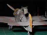
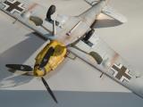
Once the wings have been mounted, the wing fairings can be attached. After putting in the very tight curvature that they require (see photos of the completed model), align them properly and then glue from the center outward. The markings on the fuselage make alignment fairly simple. Note that the wing root fairings on the original were in fact surface mounted onto the fuselage and wing coverings, which makes the final appearance of the fairings reasonably accurate. Once they are installed, the various underwing assemblies and wing cannon can be installed. (Wait until the end to install the aileron counterbalances and pitot tube.) The photo immediately above, and the underside photo at the beginning of this review show these components in place.
Landing gear:
It may be possible to make the landing gear adjustable, so that it could either be extended or retracted for display. As shown earlier, the struts are installed so as to allow them to pivot. I did not, however, see any simple way to lock the gear in extended or retracted position, so opted to glue the gear in place extended. Adjust the strut to form the proper angle with the wing, and then lock it in place with cyanoacrylate slow-cure glue. The front plan view in the instructions shows the proper mounting angle.
The wheels are built up from the usual sandwich of backed discs, but in this case with a spoked rim on the outermost disc, surrounded by a tire of slightly greater thickness. When complete, it gives a very convincing impression of a spoked wheel. It simplifies the building process to drill a hole in the center of each segment equal in diameter to the axle, and then use a piece of wire inserted through these holes to insure accurate alignment as each is glued in place. When dry, sand each "sandwich" to the correct rounded shape (use CYA glue as a stiffener if needed), and then paint, and polish them to obtain the correct finish. (I use Floquil "weathered black," really a very dark grey, for tires, and then buff it with a cotton swab after it dries.) Glue the torque links and wheel well doors in place, taking care to insure that the latter are slightly rounded to match the undersurface of the wing.
Propeller hub assembly:
Propeller assembly is fairly straightforward, though some care has to be exercised in building the individual blades. Each blade is drawn as a single part, including the front and back sides of the blade, as well as the pitch gear assembly (the pitch gears extended outside the spinner on the Bf-109E). Fold the blade halves around the mounting wire (to keep them hollow), and glue just at the trailing edges. Then roll the pitch mechanism around the wire. The plans seem to call for six mounting wires for the three blades, although there is no obvious way in which two wires could be used in a single blade. They are also shown slightly too long. Insert them into the blade to a reasonable length, glue them in place with CYA glue, and then clip off the end so as to leave about 1/32" (or about .5mm) protruding.
The propeller shaft on the "E" variant is hollow, and in the kit is made up of two nesting cylinders of equal length. Make sure they fit comfortably inside one another before installing. Form the spinner and mount the forward ring and former. Then glue the inner shaft in place (it matches up with the hole in the disk at the front of the spinner); slide on the outer shaft; and then glue the rear former in place after dryfitting the assembly with the nose to make sure there are no alignment problems. The inside of the shaft and the exposed surfaces of the nose and spinner formers should be touched up at some point during this process. Small holes can be drilled or punched in the outer shaft to help align the prop blades, which can be installed at this time. Once completed, the prop assembly can be installed by inserting the shaft through the matching holes in the first two fuselage bulkheads. No glue is needed; and while you do not get a freely rotating propeller out of this assembly, you do get one that can be easily positioned.
 Canopy:
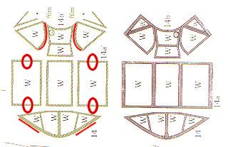
Now comes the hard part. The canopy for this model is built up in several sections, each formed as a sandwich of inner and outer framing material containing "glazing" simulated by clear styrene or some other transparent film. There are nine internal framing elements, three external pieces, and seven pieces of "glazing." An image of that section of the parts sheet is shown on the right. Cutting the parts is tedious, especially around the small oval in the forward windscreen that will accept the bomb sight (?). The problem arises from the fact that the parts fit too well, and make no allowance for the thickness of the glazing and the fact that the frames have to be folded. The red ovals in the image on the right mark areas where small amounts of material had to be removed from the central canopy section in order to insure proper alignment of the framing after the parts had been folded. The red lines in the front and back sections show where extensive trimming or sanding was required to obtain a good fit. Once the parts have been cut out, apply touch-up color to the inside edges before gluing. If you can scan and print spare copies of the parts, practice building with spare glazing material is strongly recommended.
For glazing I used .005" clear styrene for the center section. This material can be lightly scored and cleanly bent, and it will hold its shape once formed. This was important for the center section, which I intended to leave open. I used .002" film for the glazing in the forward and rear sections. I salvaged this material from the clear "window" used in my wife's pay stub mailer. Very clear, very thin, unmarked by postal processing, and extremely cheap. I am now stockpiling this material for future models. It's thin enough to work with at 1:72 scale.
Gluing the sandwiches together is tedious and presents extensive opportunities for mistakes. I finally settled on a process that went more or less as follows: (1) bend and shape all framing material before starting assembly; (2) dryfit the parts very carefully before any gluing (have spare glazing material ready in ample amounts); (3) apply very small amounts of slow-cure CYA to the outer frame; (4) mount the glazing very carefully, so that it needs no repositioning (sliding it on wet glue will ruin the surface); (5) let it dry thoroughly; (6) apply tiny amounts of CYA slow-cure glue to the inner frame components and mount them as accurately as possible and with minimal adjustment. After everything has dried, sand and trim to fit, and install the forward and rear canopy sections. It would be a good idea to install the gun sight and bomb sight at this point.
The center section of the canopy can be installed open or closed. I chose to install it in the open position to show off the cockpit interior. This also avoids any problems with fit between the three canopy sections.
Final touches:
Wherever possible, exposed cut edges should be touched up with approximately matching colors. Ideally, this would be done during the construction process, but there are inevitably spots that need additional attention at the end. I find water color pencils particularly useful. They can be purchased in delicate gradations of grey (good for this model), olive, yellow, red, etc., and I find I can apply them by simply wetting a fine watercolor brush (0, 00 or 000), picking up some color from the pencil tip, and applying it. I keep handy the pencils I will need, some water, and a paper towel or two. For surfaces and larger areas, I still like Floquil railroad and military colors. Mine are now 15 years old, and still work as well as when I bought them.
For the aerial and the lead-in to the fuselage I used .005" grey nylon basting thread, glued in place with slow-cure CYA. Insulators were simulated with small droplets of tacky glue, painted white when dry. The aerial and lead-in were given a single coat of Floquil gunmetal grey. Other than that, a little burnishing of rounded parts, shaping of slight mismatched edges, and so forth, took care of the rest. All in all, very little touch-up was needed.
Summary:
Halinski's Bf-109E is a delightful model to build, and is about as true to the original as any aircraft kit I have built to date -- paper, wood or plastic. It is immensely satisfying to complete a kit like this, and to reflect on the fact that it is made out of nothing but paper, along with a few pieces of well-hidden wire, some clear film lifted from an envelope, and a few inches of thread. If I have a complaint, it's that I wish the printing had been up to the level of the design and artwork. Not that there's anything seriously wrong with the printing. It's rather that the artwork and design together demand superb reproduction, and for this kit the printing is "merely" excellent.
This is not a kit for the novice. But it will reward the experienced builder -- and it will reward him or her very, very handsomely.
Bill Geoghegan
Copyright © 2001 by William H. Geoghegan
Return to the top of the page.
This page was created by:
Saul H. Jacobs M.Ed.
Avionics Specialist, United States Air Force (Retired)
Microcomputer Technology, Pima Community College (Retired)
Tucson Arizona
Design of the content of this page is the property of Bill Geoghegan