Dr. Ullrich Böhme HMV Verlag Cap Arcona Part 5
After I had finished to attach the main part, I started to built the many details , which can be seen of the ship. To be able to work unhindered from structures as smoke stags, I started from the bow and continued the final assembly to next deck above. The anchor winch on the Backdeck was made out of jewelry chain. The anchor hawsehole is equipment with tubes towards the Backdeck. On the anchor capstan No. 116 is a is trick wreath with spokes. This area between the spokes I have cut out, to give the whole a more realistic look. The white parts of the ventilators and the air suction machines I have build, whenever possible, from the backside to avoid the black outlines. The fork bucks of the tube winches I have cut out as well and they are therefore not just a simple paper triangle. Unfortunately I came across problems with the installation of the derrick winches. If you for example want to install part 140 and 141 you will find the corresponding outline on deck different. Therefore the winches have to be exchanged with each other in order to be installed on the corresponding position. This was also the case with some other parts in the final installation. I always had to check whether a particular part “xy” fits to the corresponding position on the deck. According to the marks on the backdeck at the transverse bulkhead there are three ventilators. On the construction diagram it shows only two. Mistakes between plan, diagram and final installation made the building more difficult and did cost time, because before each installation you I had to verify whether a particular part can be find anywhere on the sheets. The exchanged derrick winches can be found also on the astern Promenade deck. The same applies for the ventilators around the smoke stag. There are for examples markings on the deck for part 182 or for part 196 where the leg is not finished in an angle, although the part is sitting on level surface but an oblique one. For some ventilators with a t-shaped base I had to color the corresponding markings on the deck grey as the marks were drawn as rectangular shape and the T-shaped parts are smaller than the rectangular. At the ventilators 166 and 171 the substructure is missing. Therefore I had to construct a small substructure. The part 166 did fit on No. 171 but No 168 was too wide, as well as No. 173. Before installing any ventilator is was essential to check before gluing on the location to make sure whether the dimensions are corresponding. The slips of the pen complicated the construction unnecessarily. But this kind of “modeler challenges”, to say it politely, we know already from the Bremen and the Bismarck.
Before the installation of the davits and the live saving
boats I had to cut confetti. This means I had to make the railing. Because
I make railing out of single cardboard sheets and not double laminated
one, they become very thin. In order to not damage them I have build
them very late. Afterwards I made the sailcloth mounting of the ship.
At the positions of the masts they will be placed only after the installation
of the rigging of the masts and derrick, because it is easier to work
with a fewer obstacles. Differently from the instruction I have installed
already now the sailcloth framework at the walls of the superstructure
by the life saving boats, because this is very difficult as soon as
the boats are installed. As working base for the modeling work I used two glass
plates of different size which are glued on top of each other of each
3 mm thickness for the construction of the graceful sailcloth mounting.
This way I had a rectangular guide, which worked well for me. The tennis
court is enclosed with wide nets. The instructions suggest to use foil
for the nets. This solution did not seem right to me. Net has to be
net. I found in my Christmas funds a green, transparent ribbon, which
would fit exactly in the green and transparent structure. The ribbon
had only one disadvantage. When you cut it, it disintegrates. I have
therefore placed it on an even surface and sprayed with varnish and
let it dry well. Meanwhile I installed the posts for the tennis court.
Original pictures of the tennis court show that the net was divided
between the posts. One time they lead from the upper edge of the dingis (which means the fix enclosure of the place similar as the band in Ice hockey) until there the beveled post and the vertical post are connected through a crossbeam and on the other side where the beveled strutting meets directly the vertical post. Further one was the post overhead strained with steel wire and fixed on the deck. On these locations I have glued 0.5 mm wire over the whole length of the sides and then glued the nets, cut to size, inside. I have erected nets around the four corners according to the pictures. Now I had to work on the davits and boat. As I installed the davits I had to learn the boxes of the Jacobs ladder did not fit well into the gap on the davits. The marks on the ship’s side and the boats deck do not fit to each other. The remaining parts did fit aft and back. To conceal the error I have used parts of the grey stripes of the boats deck, which I had scanned previously. I have glued over the white marks for the davits on the „wrong position“. I did make a template of the marks of the different detailed parts before that. The construction of the davits did not cause too much
problems. The holes in the stanchions of the platform are stenciled
out and the step ladder is made out of fly net. I have cut out the grey
triangle at the mounting of the fulcrum shaft. This increased the authenticity.
Unfortunately it is not visible in the drawings how
steep the davits boom have to be attached to the shaft. The photos indicate
a nearly vertical position. The building of the boast did work normally.
At the oars, which are included with the open boats, I have cut out
the space between the oar rods. At the boats which are covered with
tarpaulin I have made the contortion of the sailcloth as follows. At
the side in view of the tarpaulin, that means outboard, the earing is
glued backward on the triangles and on the side toward the hull on the
triangles. Here you do not see it anyway. At the mast of the cap rings are provided at which the stage should be glued on. I have glued first the shroud and stage on the marked positions and then glued the rings, which are a little longer than required, over the ends of the rope. I was very good that I have glued with the mounts of the sheer poles on to the deck. It was already difficult enough with the room limitation to get the threads through the mounts. I would have been much more difficult, if I had glued the threads directly to the deck. Unfortunately in case of the Arcona as with so many other models even of other publishers the precise rigging is a step child. The model is obviously researched well, but how to fasten the rope will not be told. Here is much room for improvement. The ladders on the mast are again made with the confetti method. Sofar my report of today. |
|
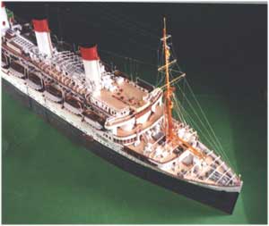
Front Part of the Ship |
|
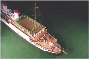
The empty ship astern |
|
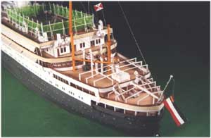
The bridge of the ready ship. Note the Jacobladder and flag under the bridge |
|
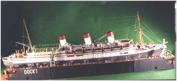
Mid ship section |
|
The bridge from front with dinghy |
|
The front section from top |
|
Easy to recognise the lining of the tennis court |
|
The balconies for the davits. Easy to see the cut out and holes |
|
This is not a battery of old MG but the davits spindel |
|
The davits balcone. You can see the ladder |
|
Side view of the tarpaulin support |
|
Progress of the support |
|
The finished backdeck |
|
|
|
|