Photos by the author
Last month I received the latest kit from Roger Pattenden. This is a change from his usual kits, it's the inside and not the outside of a building!
He tells me that the kit came about because the Kew Bridge trust commissioned him to make a kit of their famous engine. Those of you who read last months review will note that I have taken a well earned break from my current project. It's certainly a welcome change. The only problem is that "I hate tubes" and as you will see there are about twenty in this kit, varying in size from half and inch long to almost 6 inches.
The card is a little on the thick side, especially for the smaller parts but not so for some of the larger parts. The style is typical of Roger, it's hand painted and printed from the original. This makes painting and touching up much easier than with many other kits. There are no real problems with the kit, but it's not one of the easiest I've made. Like the other kits from Roger, the pieces are constructed in numerical order.
So, with no more ado I give you�� Roger's Pump.
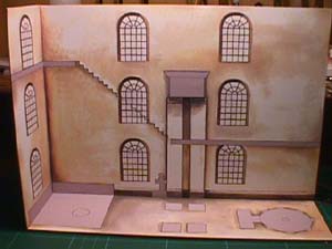
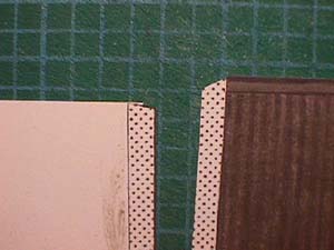
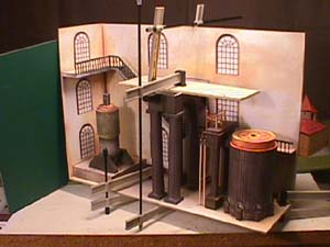
The first parts of the kit make up the two outer walls and floor. All three
of these were reinforced to make attaching the following pieces a little easier.
This is the main staircase that goes up the back of the building. The instructions
say that the more experienced modeler may like to cut out the "D" shaped pieces
needless to say I went one step (please excuse the pun) further and cut out
the small triangular pieces as well. One small comment at this point�. The markings
on the edge of this piece show where the scoring is to be made, however it does
not differentiate between valley and hill folds. Not a problem for an experienced
modeler but may be not so good for someone who has bought the kit as perhaps
a first timer.
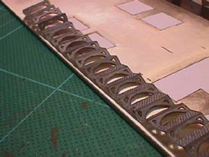
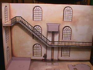
The stairs and railings are now installed, as you can see I spent ages cutting
out the railings just so you can see the cut outs in the stairs! I think the
time was well spent. It adds a light touch to the model and contrasts very well
with the heavy machinery that follows.
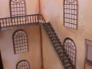
Another view of the stairs.
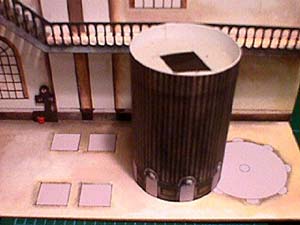
Here comes the first of the tubes! As you will see I have used home made
templates to help keep the piece on shape. This part is the steam chest. The
steam is pushed in to the top of the chest under high pressure, this pushed
the piston down thus raising the pump on the other side.
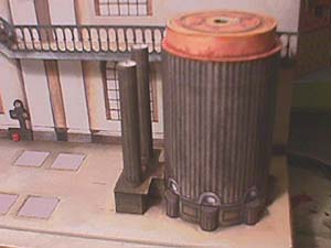
I have moved on quite a bit and as you can see, we now have 4 tubes. Also,
note the small piece in the background. This is the fire point, I made a small
piece of card to give a 3 dimensional effect to the fire bucket.
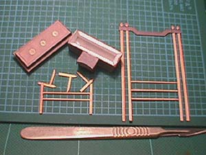
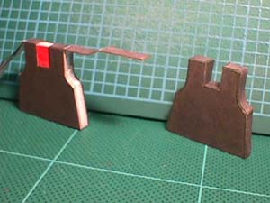
These pieces make up part of the control mechanism. Roger deliberately kept
this part simple. On the real engine it is made up of dozens of levers and handles
that regulate the speed of the steam injection and condensing. Yes, I was tempted
to have a go at adding more bits but then thought better of it!
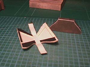
Not a very good picture I'm afraid. This one attempts to show how this piece
was constructed. As with quite a few parts, there are no tabs. I admit that
as a rule I tend to cut off quite a few tabs but generally they are a necessary
part of a model. Rather than try to butt joint the thin card, I glued in a few
pieces of thicker card so that the sculptured sides would be easier and more
accurately glued in place.
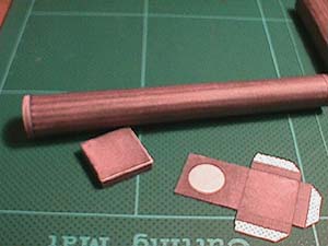
Here I am showing how I made some of the tubes, I cut off the tab and re
glue it inside the piece. I then roll it and because there is now a "step" in
the card it is easier to locate and gives a smooth finish
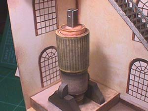
Another jump forward. Here is the "water raising" side of the engine. The
injected steam to the chest raises this side of the pump and the force of gravity
lowers it when the steam condenses in the chest on the other side�Simple isn't
it ??. The workings may be easy but as you can see this side of the pump consists
of yet another heap of tubes. Luckily the fit of the parts is excellent and
the instructions are good enough to make this section reasonably easy. I particularly
liked the paintwork. It gives the piece a real "heavy" look, just what you want
in an industrial model like this.
The next few pictures show the making of the "fulcrum" of the beam. This
shows yet another series of tubes!
The two parts that make up the main load carrier of the beam don't have
tabs and again I made up some templates. This time I used a piece of "foam core"
I added a thin piece of card to give it the right thickness.
I use my own variety of scaffold poles to hold all the pieces in
place and to ensure that the main pillars stay vertical until the glue dries.
These four pillars are the main focal point of the model and must be upright.
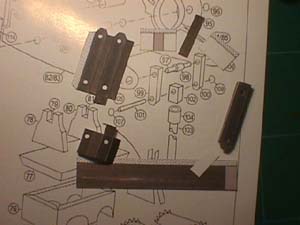
Here we have the parts that make up one of the two beam-ends. A lot of time
was spent ensuring that these pieces moved easily. The instructions are included
to show how easy they are to follow. Pic 15 shows the hinges in place, minus
the end caps. Again, Roger deliberately left off the rather delicate extras
that are found on the original. A good idea !!
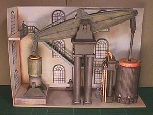
The completed model including the two figures that come with the kit.
Industrial Archaeology is an interest of mine and so it was a pleasure to build the pump. I said at the start that I hate tubes, I still don't like them but it was well worth the effort. Roger's kit is an unusual subject and it is well up to his high standards of design. The coloring is just right for this piece of working history.
Thanks to Roger for the kit. I hope that The Kew Bridge Trust like the kit as much as I do.
